Articles, Tips & Tricks and Tutorials

Jewellery CAD Standards that every designer should know
In this article, you will learn about the tolerances and limitations in different stages of the production process that you need to consider when designing jewellery in 3D software packages. It includes minimum metal thickness in different parts of a design, shape and size of the holes, creating different joints and connections, considering the effect of the shrinkage during the design process and learning more about the casting process and how to prepare 3d models to achieve the best results in casting jewellery.
One distinction between 3D jewellery modelling and other types of 3D modelling is that 3D models must be developed not just to be 3D printed but also to effectively complete the manufacturing process, including casting and stone setting. As a result, a CAD designer must be thoroughly conversant with the procedures of manufacturing jewellery as well as relevant CAD standards, in addition to mastering 3D modelling. The majority of these jewellery manufacturing standards that every 3D jewellery designer should be aware of are covered in this part. It should be noted that a substantial portion of the values presented in this section is based on my personal experience as a CAD technician and on trial and error. These standards, however, might differ based on the technology and equipment utilised in 3D printing and jewellery production. If you have access to technicians in various manufacturing departments, such as casting technicians, goldsmiths and stone setters, I recommend that you check your design with them before manufacturing so that, if necessary, you can make the necessary changes to the model regarding the machines and methods used to create them to ensure the success of your design.
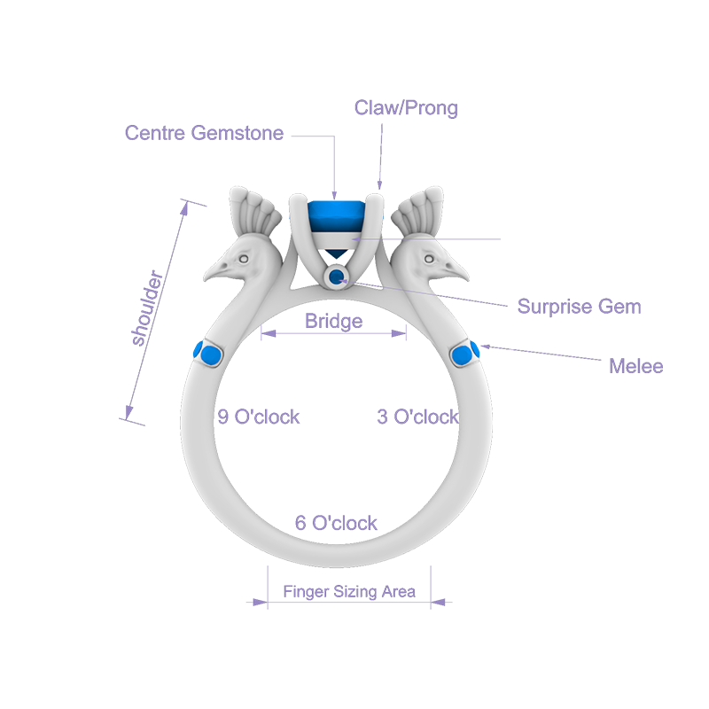
Anatomy of a Solitaire Ring
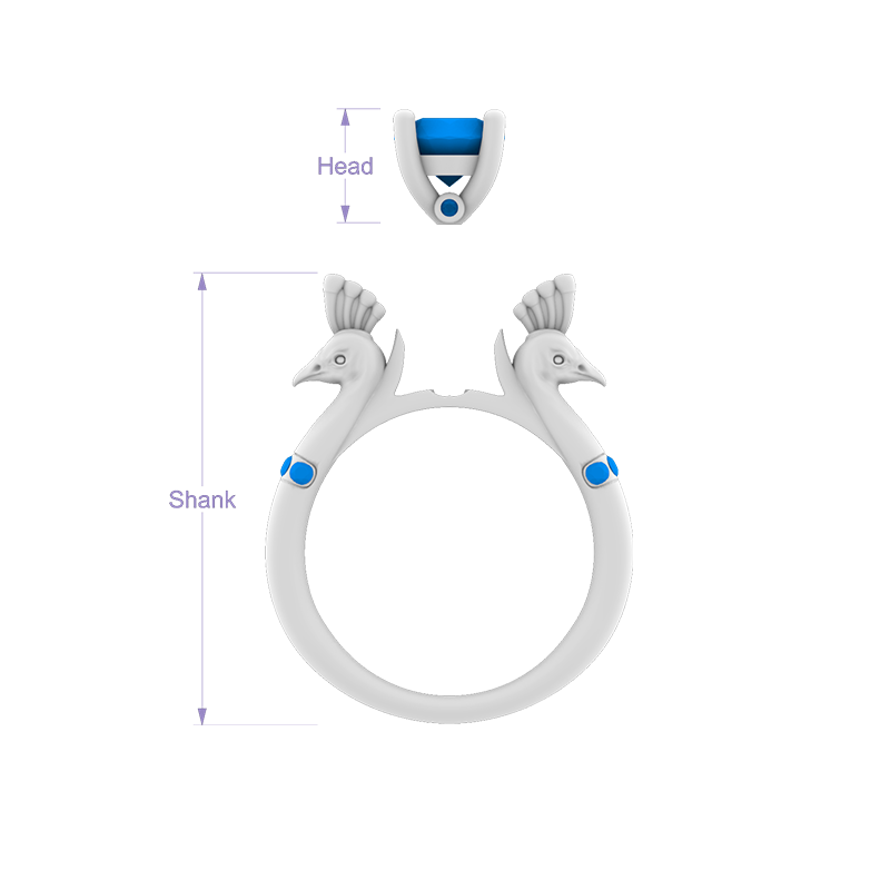
A two-part ring is made of Shank and Head
Thickness and main dimensions
The minimum thickness and distance in various design portions are among the most significant factors to consider while modelling. If the given sizes are less than a specific value, the product will have issues during or shortly after manufacturing. If these amounts are excessively large, the weight of the design and price will increase. Throughout the modelling phase, it is critical to contemplate and predict changes in the size and thickness of the model that may occur during the manufacturing phase. For example, throughout the cleaning, stone setting and polishing steps, the thickness of a computer-modelled design is normally reduced by an average of 0.10 mm on each side (a total of 0.20 mm). If this drop in thickness is not predicted during computer modelling, the jewellery will likely be too thin and weak after manufacturing.
The thicknesses of various parts of a ring
At the time of modelling, it is advised that the ring thickness in the sizing area be at least 1.40 mm. Take the ring's bridge thickness 1 mm or greater. As previously stated, these values will drop by approximately 0.10 mm on each side for a total of 0.20 mm after completion. A thickness of more than 2.50 mm produces gaps between the fingers and discomfort when worn, especially for an extended period. A ring wider than 16 mm may also keep the finger from bending.
Key point
It is preferable if the bottom area of the ring, known as the sizing area, has a plain cross-section with no unique design so that the ring's size can be reduced or expanded as needed. To lower the size of the ring, the jeweller saws and cuts off the ring bottom, bends it and then welds the two ends together. It is possible to increase the inner diameter of a ring by one or two units by employing a special tool for adjusting the size (a ring stretcher) and applying tensile force. The ring size section is normally sawed to raise the size by more than two units, and a metal strip with the same profile is attached.
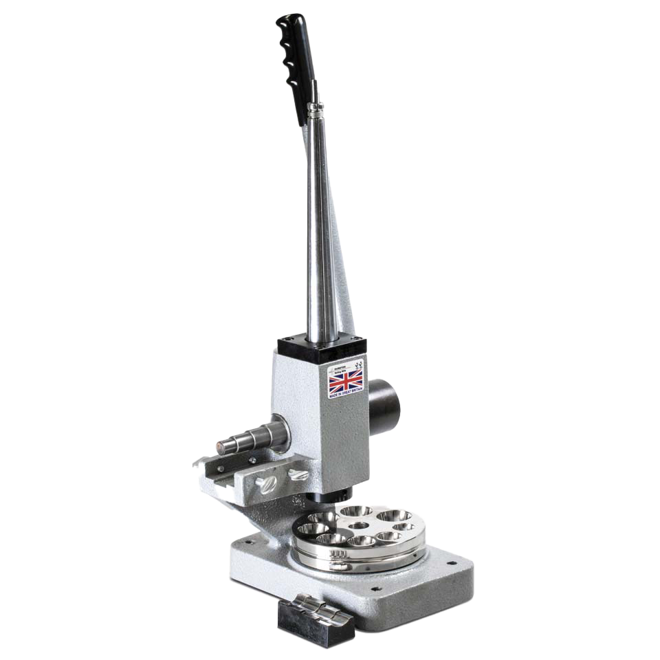
Combination Ring Stretcher Reducer Bender
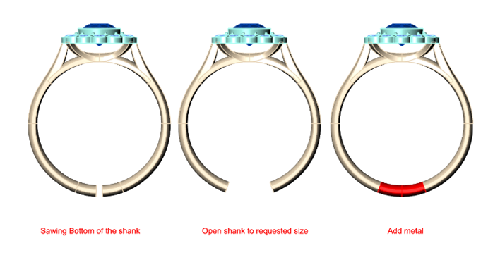
Steps to increase the size of a ring manually, Image Credit: Domino Jewellery
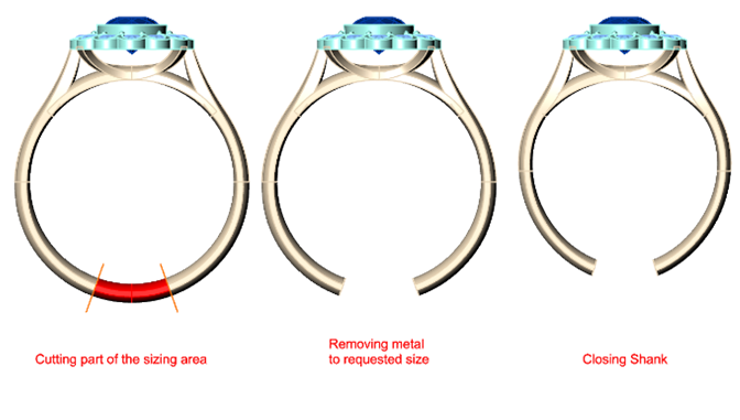
Steps to lower the size of a ring manually, Image Credit: Domino Jewellery
Maintaining a plain and adjustable ring bottom will make the design more commercial and enhance product sales. Assume a consumer likes a ring, but it is too small for their finger. If the ring can be resized, the jeweller quickly changes the ring size and offers it to the customer, eliminating the need to make a new one.
Minimum thickness of metal
Minimum thickness of metal
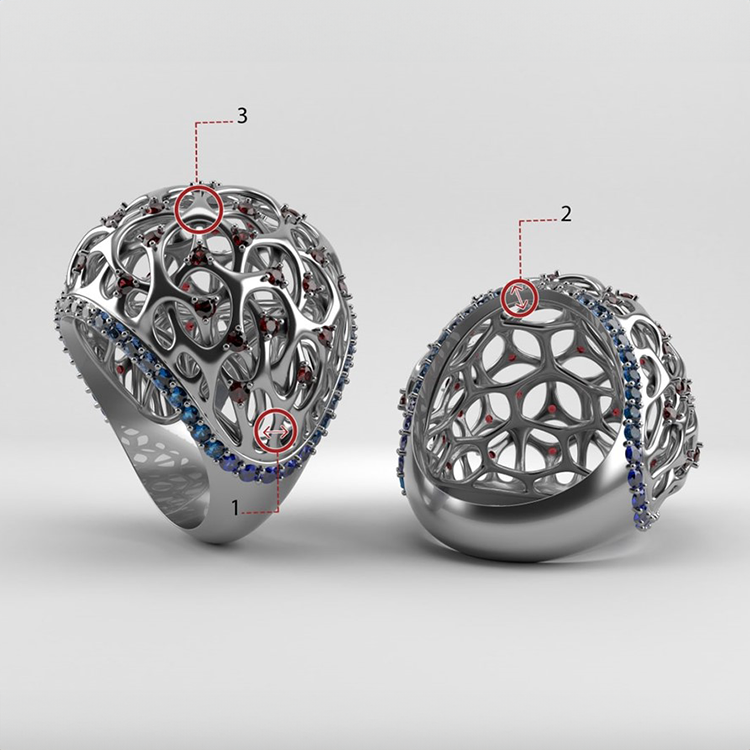
In general, the thickness of the metal used in the design's key elements should not be less than 0.60 mm after manufacturing. Considering the thickness decrease of around 0.10 to 0.20 mm for each design throughout the manufacturing process, the minimum thickness of the 3D model should be 0.80 mm. However, for small or subsidiary components, such as jump rings or wires less impacted by the thickness reduction in the manufacturing process, a minimum thickness of 0.50 mm should be considered (number 1 in the image).
The outer walls
Typically, the outer walls of a design, particularly a ring, are more vulnerable to impact, friction and pressure than other elements, and they lose some of their thickness over time. Set the minimum thickness of the outer walls (number 2 in the image) at 0.80 mm in the modelled design to boost the strength and endurance of the jewellery. However, if possible, elevate this value to 1 mm or greater to extend product life and lessen the vulnerability of the main design components.
Overlapping
To improve the strength of a design with small parts, high delicacy and low thickness, the model's components should overlap by at least 0.20 mm (number 3 in the image).
The gap between design components
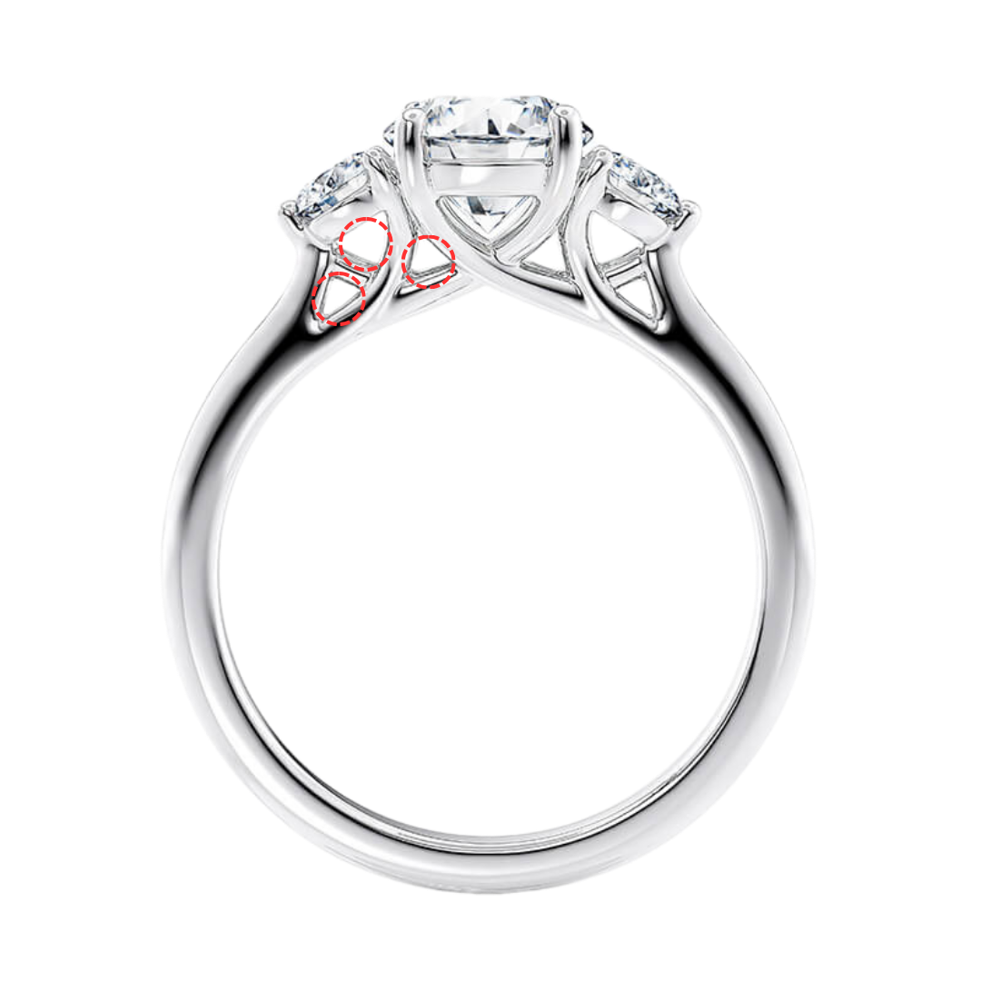
Set a minimum gap of 0.50 mm between design components to have a successful moulding by preventing filling gaps during the casting step.
Raised letters
To achieve a superior casting outcome, the following are preferable:
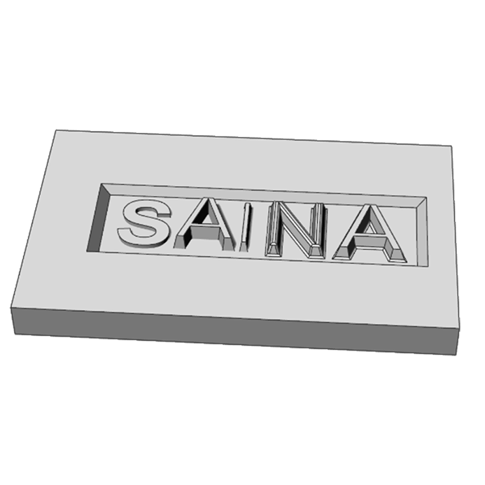
1. The cross-section of the raised design should be positioned on the metal surface at greater than 90 degrees. The letter S in the illustration has a 90-degree angle, while the other letters have angles more than 90 degrees to their bottom surface.
2. Soften all the edges of the letters, including the shared edges between the letters and the underlying metal, with the Fillet command (as shown in the illustration for the letter N). This helps smooth the molten metal flow inside the mould and avoid any casting issues.
3. Consider the raised designs to have a minimum thickness of 0.30 mm and a maximum height of 0.60 mm. The illustration's second letter (A) is more than 0.60 mm high. Furthermore, the third letter (I) has a thickness of less than 0.30 mm.
4. Set a minimum gap of 0.30 mm between the components. This value is less than the distance between the letters I and A.
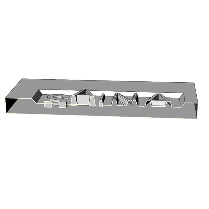
Raised letters with different thicknesses and heights
5. If the raised designs are on a recessed surface, they should be 0.10 to 0.20 mm higher than the side walls to be readily cleaned during buffing and polishing (two raised designs on the right side of the image). After buffing and polishing, the excess thickness reduces and lies level with the side walls. If the raised letters and designs are shorter than the surrounding walls (as seen in the image by the red raised design), cleaning the surface will be more challenging and time consuming.
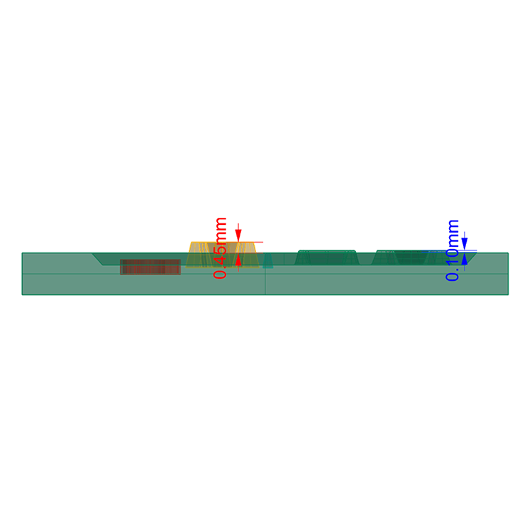
Raised letters with different heights than the side bezels
Recessed letters and designs on metal
1. To prevent casting issues, the cross-section of the designs that have been subtracted from the metal surface should have an angle of less than 90 degrees to the metal surface, and the bottom edges of the design should be filleted.
2. The recess of the metal must be at least 0.30 mm deep.
3. The recess depth should not be greater than twice its breadth.
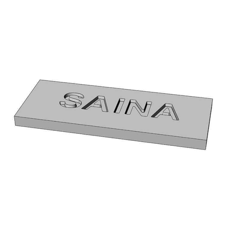
The formed letters have sharp edges and vertical rims.
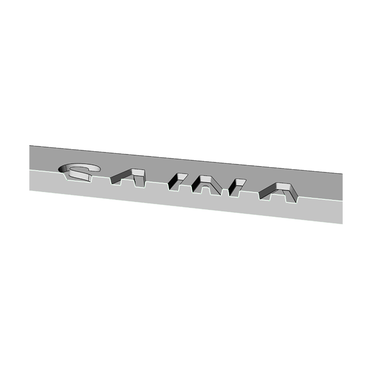
Most of the recess edges are filleted, and the letter rims are at an angle of more than 90 degrees to the horizon.
End of this article
Thank you so much for investing your precious time to read this article. I hope you found this it useful.
I invite you to join the email list, so I would be able to send you updates about the new tutorials, articles and downloadable resources.
If you have any question, you can be in touch with me. Happy to help 🙂 hi@hamedarab.academy
In the next article:
I will share some tips and tricks about making pilot holes and divot cutters in CAD. Also, I will share some useful information about creating millgrain in CAD and mistakes you should avoid.
The next article would be shorter that this one, but very valuable.
Take car,
Hamed
Would you like to receive the latest tutorials, tips & trick in your inbox?
